Cm4 94v0 Boardview Exclusive !link! Page
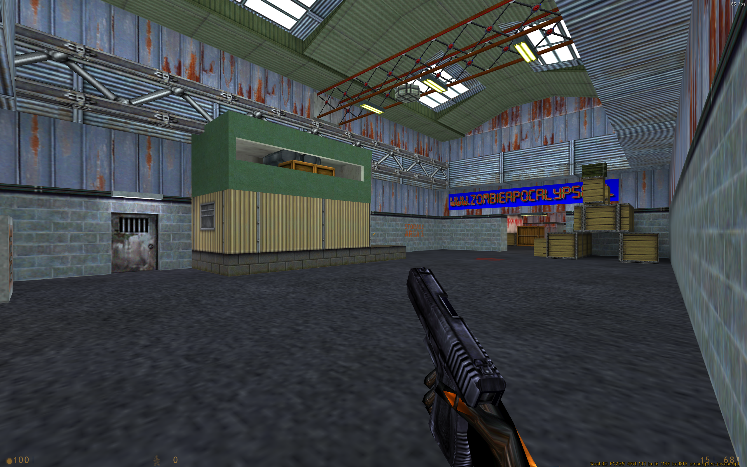
Identifying resistors, inductors, and ICs by their reference designators (e.g., U1, C20, R5) to replace them using a hot air station. 2. Custom Carrier Board Design and Signal Integrity
Locate the main PMIC inductors and verify voltage output stability.
The Raspberry Pi Compute Module 4 represents a paradigm shift from its predecessors. Unlike the DDR2-style SODIMM form factor of the CM3, the CM4 integrates the processor, memory, and optional eMMC/WiFi into a compact module. Because the CM4 is designed to be embedded into custom carrier boards rather than used as a standalone consumer device, official schematics for the module itself are proprietary and closely guarded by the Raspberry Pi Foundation. This scarcity drives the demand for boardview files. cm4 94v0 boardview exclusive
Shifting from the physical board to its virtual blueprint, a "Boardview" file is the universal language of PCB repair and diagnostics. It is a file format used to represent the layout of components on a circuit board and their connections.
Click any pin to highlight every interconnected component on the board. 3. Common Failure Points on CM4 94V0 Boards Identifying resistors, inductors, and ICs by their reference
If the module boots but a peripheral like the Gigabit Ethernet port fails, locate the Broadcom BCM54210PE PHY chip on your boardview. Check the clock signal line (25 MHz crystal oscillator) and ensure the specific 1.0V and 2.5V power rails dedicated to the network chip are operational. Common Fault Points on CM4 Carrier Boards
Follow these steps to open and utilize your raw boardview data files: The Raspberry Pi Compute Module 4 represents a
Is this the , or a third-party carrier board (like BigTreeTech, Waveshare, Seeed Studio)?
Most CM4 94V0 boardview files come in the following formats:
If a schematic tells you how the components are connected , a file tells you exactly where those components are located physically on the board.
When repairing a complex multi-layer PCB like a CM4 carrier board, standard schematics only tell half the story. Circuit Schematic Boardview Diagram Shows how components connect logically. Shows where components sit physically. Trace Visibility Represents connections as straight lines. Maps exact copper traces across PCB layers. Pin Mapping Lists pin numbers in an abstract grid. Highlights exact physical pins and via locations. Best Used For Understanding voltage rails and logic flow. Locating hidden shorts and broken traces.